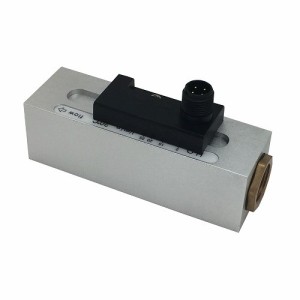
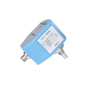
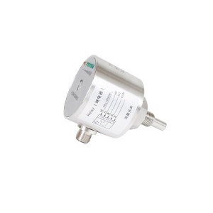
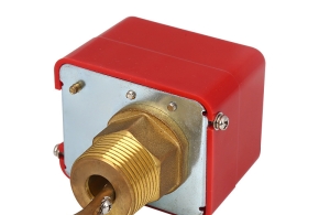
FS series liquid flow switch is designed for managing the flow changes when the liquid flows in the pipe, such as water, ethylene glycol or other non-hazardous liquids. When the liquid flow is higher or lower than the setting value, the single-pole double- throw contacts (SPDT) can get through one circuit and at meantime to break the other circuit. FS series liquid flow switch is commonly used for chain reaction or “no flow” protection.
Features
Max liquid pressure: 1 MPa, can be used in multiple applications.
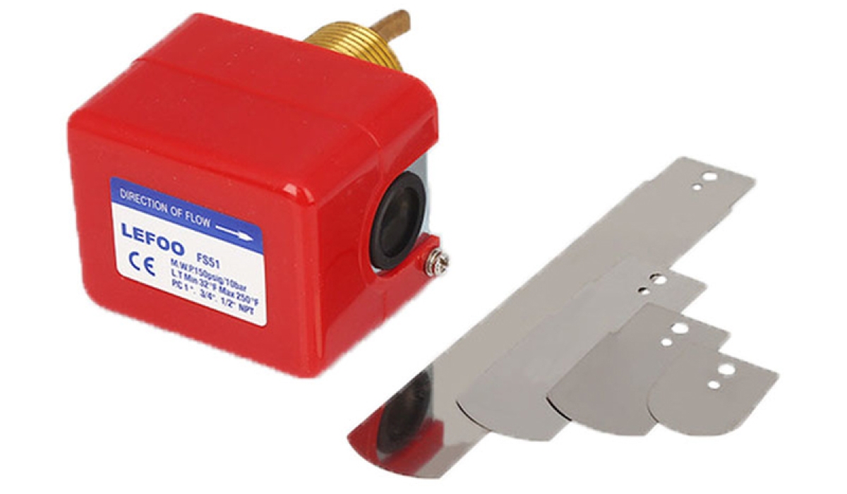
There are 3 stainless steel paddles, can be used in 25 to75mmdiameter pipe.
Number of paddles is changeable and length of paddle is trim-able according to customer requirements.
With additional 6" paddle, FS series liquid flow switch can be used in 100 to150mm diameter pipe
Adjustable flow setting, Users can set the flow value according to their requirements.
The cover of FS52 flow switch is fully enclosed. This structure is effective for electrical equipment against the water and dust. (A little condensation is allowed). As FS52 flow switch is indivisible and fully enclosed, a little condensation will not lead to electric leakage. For user convenience, FS52 flow switch has large room for wiring.
FS51/FS52 can also be provided with stainless steel connection, which is suitable for ammonia and other medium.
|
|  | |
| FS51 | FS52 |
Application
The typically application is used to protect the cooling system, when the cooling water is off, FS flow switch can shut off thecompressorcurrent efficiently in order to protect the freezer and entire system from being damaged.
Specification(FS flow switch)
| Actuate flow?m³/h? | |||||||||||||||
| Pipe Diameter?mm? | 25 | 32 | 40 | 50 | 65 | 80 | 100 | 125 | 150 | 200 | 100* | 125* | 150* | 200* | |
| Min Adjustment | Flow increase(red blue closed? | 0.95 | 1.32 | 1.70 | 3.11 | 4.09 | 6.24 | 14.8 | 28.4 | 43.2 | 85.2 | 8.4 | 12.9 | 16.8 | 46.6 |
| Flow decrease (red yellow closed? | 0.57 | 0.84 | 1.14 | 2.16 | 2.84 | 4.32 | 11.4m, | 22.9 | 35.9 | 72.7 | 6.13 | 9.31 | 12.26 | 38.6 | |
| Max Adjustment | Flow increase (red blue closed? | 2.0 | 3.02 | 4.36 | 6.6 | 7.84 | 12.0 | 29.1 | 55.6 | 85.2 | 172.6 | 13.4 | 26.8 | 32.7 | 94.26 |
| Flow decrease (red yellow closed? | 1.93 | 2.84 | 4.09 | 6.13 | 7.23 | 11.4 | 27.7 | 53.4 | 81.8 | 165.8 | 17.3 | 25.21 | 30.66 | 90.85 | |
1. Above flow values are for the reference of choice
2. The figures with “ * ” symbol are for the 4 paddles flow switch. While, the figures without “ * ” symbol are for the 3 paddles (1, 2, 3 ) flow switch.
3. The paddles will be chose according to the flow in the main pipe where the flow switch is installed in.
Performance Parameter
Electric load : AC250V 10A
Max working pressure: 10.34Bar
Flow temperature: 0-120?
Environment temperature: 0-60?
The endurance of bellows: 500000 cycles
Ingress protection: IP53
Installation
1. Pipe connection: FS series flow switch be provided with 1", 1/2", 3/4" NPTconnections.
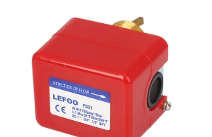
2. The arrow direction in the cover must be as same as the flow direction in the pipe.
3. The flow switch is suggested to be installed on horizontal pipes, if it have to be on vertical pipes, then the direction in the pipe must be upward flow. It is not allowed to be installed on the vertical lines with downward flow.
4. To avoid the paddle damage, flow reversal is not allowed when the flow switch is working.
The paddle trimming figure

Attention: the paddles with “ * ” symbol are installed in factory/
the paddle with “?” symbol is the additional paddle.(not installed)
the balance paddles are for trimming
when install the trimmed paddles, the end of paddle should keep 5-10mmdistance from the pipe end and no friction with the pipe
Wiring diagram

Typical installation drawing


.png)


